The k factor is the ratio of the neutral axis location t to the material thickness mt.
Catia sheet metal k factor.
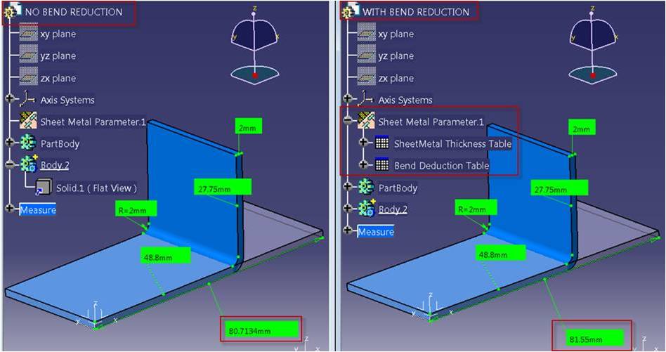
Cad tools use k factor to calculate sheet metal blank size.
Catia an acronym of computer aided three dimensional interactive application in english usually pronounced multi platform computer aided design cad computer aided manufacturing cam.
The line where the transition from compression to stretching occurs is called the neutral axis.
Mathematically k factor is a ratio of position of neutral axis and sheet thickness.
The k factor is the ratio of the neutral layer position thickness t of the sheet metal to the overall thickness of the sheet metal material t i e.
K t t why the k factor cannot exceed 0 5.
When you bend sheet metal the neutral axis shifts toward the inside surface of the bend.
From this video will we start catia v5 generative sheet metal design tutorials series.
Value of k factor is always less than 0 5.
You can also use our flat pattern calculator for blank size calculation.
In this tutorial you will le.
1 introduction sheet metal introduction 2 primary walls and secondary walls 3 sheetmetal parameters 4 k factor and y factor 5 various sheet metal tools 6 creating sheet metal components.
Best way to calculate k factor in sheet metal is by reverse engineering.
After bending the sheet insert the inner radius and flanges a and b.
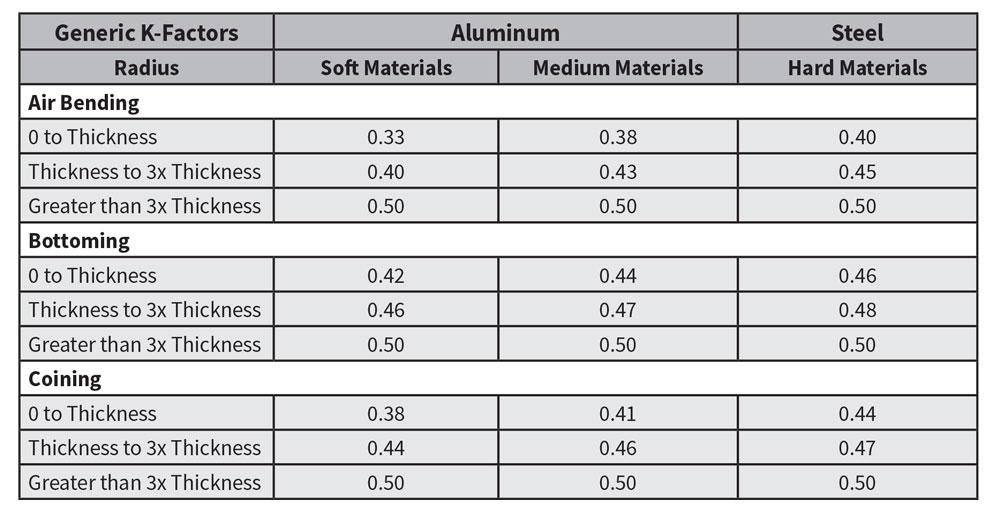
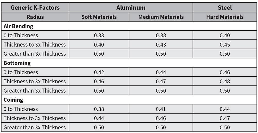
We produce a lot of sheet metal work using invento and use 0 2732 for below 3mm sheet and 0 3365 for 3mm and above using ilogic we automatically set the k factor depending on the thk of material so we don t forget to adjust it each time.
To calculate the bend allowance the k factor and the derived coefficient called the y factor insert the thickness and initial length of the sheet into the cells on the left.
Our design engineers typically use a factor of 0 4 for our air formed press brake parts.
Catia sheet metal tutorial for beginners.
K factor is a constant used to calculate the sheetmetal flat length.
The k factors mentioned are to suit our own press and tools of course.
When metal is bent the top section is going to undergo compression and the bottom section will be stretched.
The k factor in sheet metal working is the ratio of the neutral axis to the material thickness.
Sheet metal depends on certain parameters 1 thickness 2 bend radius 3 bend angle.
I had a question on k factors for our 3 d modeling software.
Definition of the k factor.
L ᴫ 2 r y t θ 90.
You can use this k factor calculator to calculate k factor using reverse engineering method.